
I bought six DGX Sparks to run AI inference around the clock. Inference is the work of running a model to produce answers, and in my setup, that work does not stop when the business day ends.
The machines ran hot. They were also expensive, and I wanted them to last as long as possible. That was enough reason for me to start building a better cooling arrangement.
Looking back through the dated designs and print logs, I group the builds into four versions leading to the cases I use now. AI helped me design them, check them, and operate the 3D printer. I handled the physical work, including discovering that a design which looked finished on the screen still needed changes after printing.
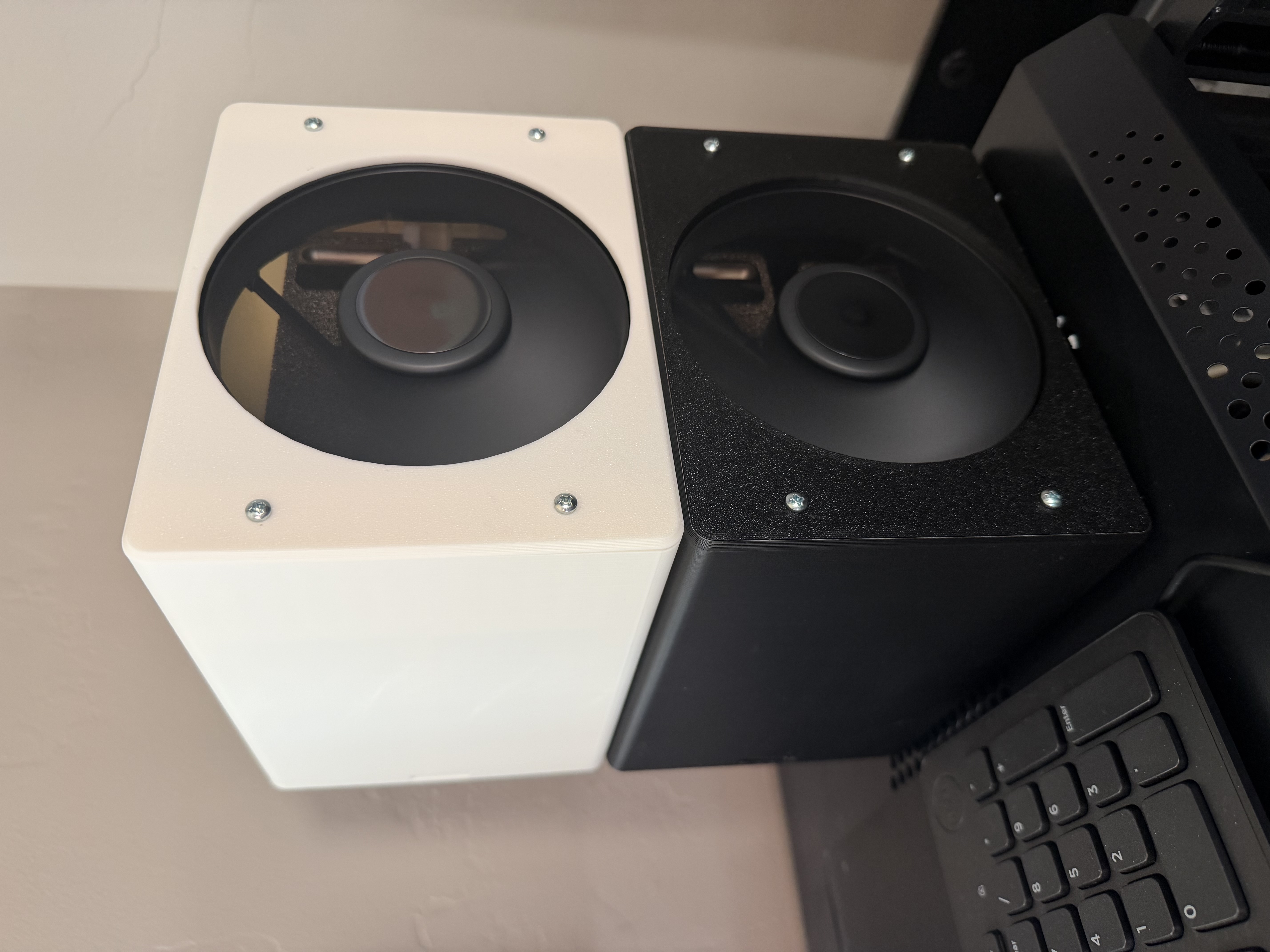
Version one had too many pieces
The first idea was a tight wind tunnel with air exhausting out the top. The Sparks stood on edge in separate sections connected to a rear chimney and fan.
The parts were printed by September 6. There were cells, lids, end caps, connecting pieces, and cable plates. I had to glue the assembly together, and all the pieces and gaps made it unruly.
I wanted something simpler.
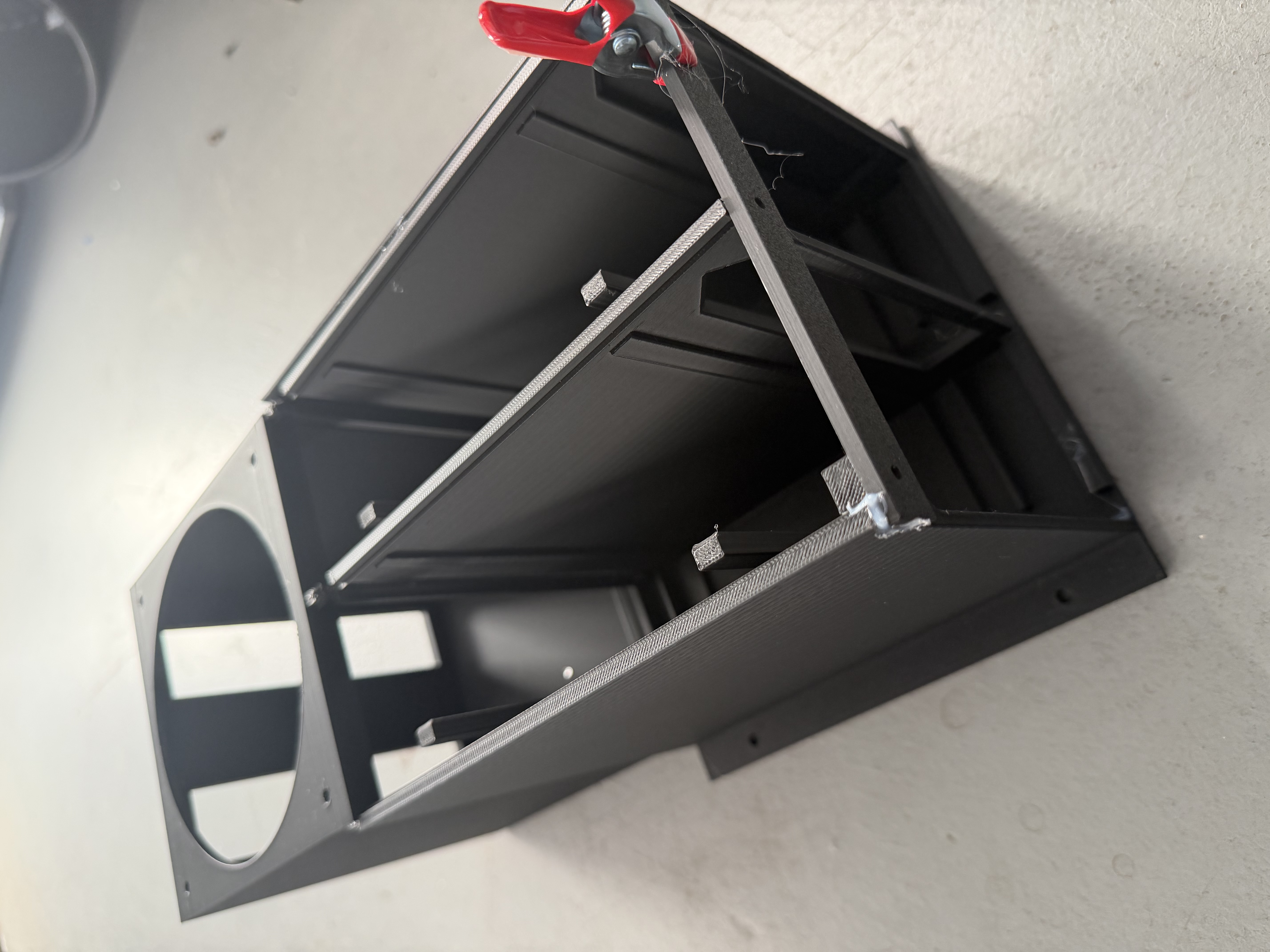
Version two put the upright pair inside a smaller box
The next design kept the two Sparks standing upright but replaced the larger assembly with a main shell and a bottom plate. The fan sat inside the top of the box, beneath a honeycomb grille.
The full shell and bottom plate finished printing on September 8. The smaller arrangement was a step toward what I wanted, but the physical parts exposed problems we had missed.
Some side openings filled with printed support material. The front openings came out 6 mm too short because the design did not account for the height of the supports beneath the Sparks. The computers also sat too loosely, and reaching the power button and routing cables were awkward.
A smaller box was not enough. The machines needed to fit securely, and I still needed to plug them in and use them.
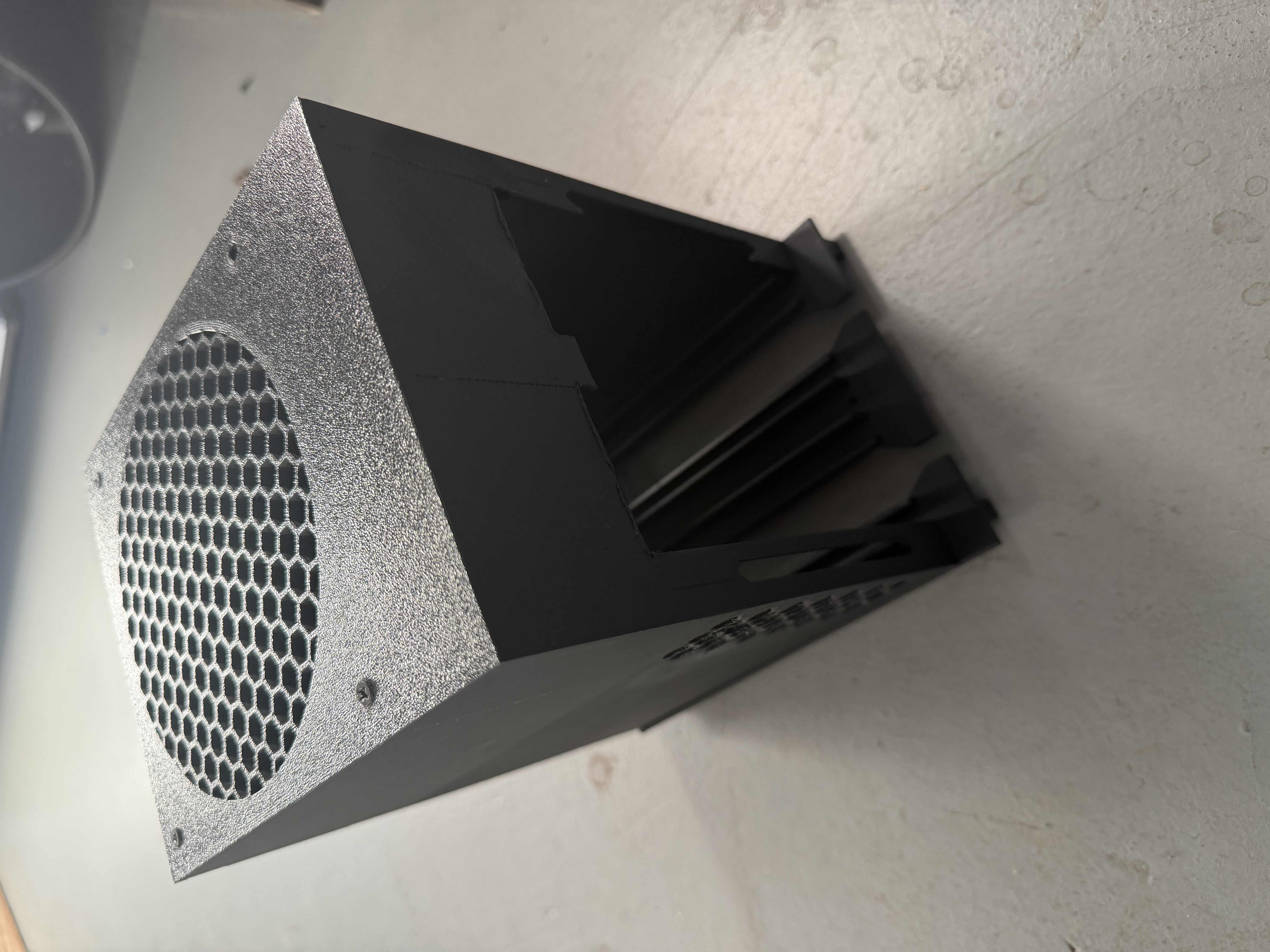
Version three stacked the Sparks, but the middle tray caused trouble
On September 9, the design changed more substantially. Instead of standing the Sparks on edge, we laid them flat and stacked one above the other. A fan at the front pushed air toward an open rear, where the cables connected.
This first stacked version had a tray between the machines. It also started with hooks for the front fan cover and a friction-fit retaining bar at the back.
The tray was a problem. One print had support material fused to it. In a later fit check, the tray arrangement was still 2–3 mm too thick. I had to remove a bottom cover from one Spark to get the second machine into that earlier case.
That was a workaround, not the design I wanted to keep. I also wanted screws holding the assembly together rather than relying on hooks and friction.
Version four holds the machines from the sides
The final design removed the middle tray. Supports along the side walls hold each Spark securely, with space around the bodies and between them.
We reinforced the ledges carrying the weight and used screws for the front cover and rear retaining bar. Then we made another small but useful change: the solid rear bar crossed the air gap between the Sparks, so we added seven rectangular openings through it.
The first successful set of this design was finished on September 12. The white set followed on September 13, and another black set was completed on September 15. The later sets included the vented retaining bar.
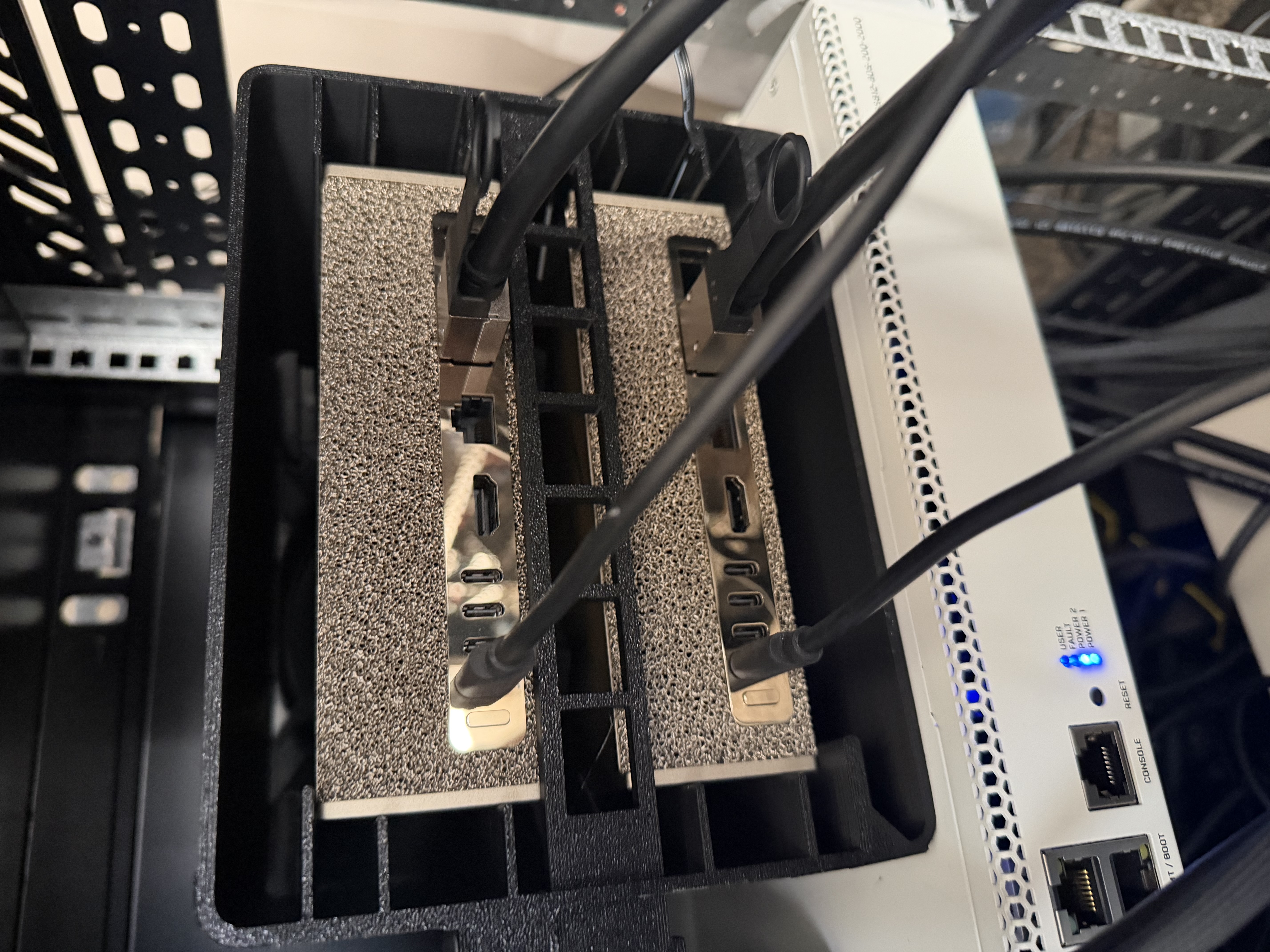
I have now built three of these cases for all six Sparks. They are functional, the machines fit tightly, and they run significantly cooler in my use, including at full load without underclocking.
I tried a quiet fan and a higher-RPM fan. RPM is the fan's rotation speed. I ended up choosing the higher-RPM option and running it at roughly half throttle because it moved more air in my comparison while remaining quiet enough for me.
That is my assessment of the setup, not a measured sound-level or airflow rating. The useful setting was the one I was willing to leave running.
AI caught errors, but the printed parts still needed testing
My process started with telling AI what I wanted. It drafted alternatives and digital renderings, and I went back and forth with it until I liked the design.
Then I had different models review it repeatedly. They found plenty of errors. We corrected them and kept reviewing until those checks stopped finding more.
Printing was a separate test.
Parts still failed to fit perfectly, or I found something that needed changing once the hardware was in my hands. The tray was one example. The short openings in the upright box were another.
AI also handled the printer operations after I told it the printer was ready. I still had to clear the plate, deal with filament and nozzle problems, remove supports, assemble the parts, and check the fit.
That division worked for this project. AI handled the digital work, but I did not have to pretend the renderings proved the physical design was finished.
The temperature records show about a 10°C average difference
We ran a cooling comparison on September 9, before the later stacked cases were printed. The intended test was five minutes of four parallel Qwen requests across four Sparks, with the earlier GPU clock limit removed.
The original test report identifies two machines as being inside a wind-tunnel enclosure and two as the comparison machines. The saved file contains 21 rounds of GPU temperature readings.
| Machines identified in the test report | Average across the recorded samples | Highest recorded temperatures |
|---|---|---|
| Enclosed pair | 49.17°C | 53°C and 54°C |
| Comparison pair | 59.40°C | 66°C and 69°C |
Subtracting the two unrounded pair averages gives a difference of about 10.2°C across the recorded samples. That is the observed temperature gap between the two pairs, not a measured before-and-after reduction on the same machines.
There are limits to what this test tells us. These were different machines, and the enclosed pair started cooler. Their recorded clocks and power readings also differed. We did not record the room temperature or fan setting in the test files, and the records do not identify the exact earlier enclosure being tested.
It was not a controlled case-on, case-off test of version four. It also does not tell me how many extra years the machines will last. Longer life is why I started the project, not something this short temperature test can prove.
Clock speed was a separate experiment
I also tried reducing the Sparks' GPU clock speed to around 1,900 MHz. In my testing, I could retain the throughput I needed while getting significantly lower temperatures.
That is a separate observation from the enclosure comparison. I would not assume the same setting preserves performance for every model or workload, and the September 9 case test does not establish that result.
For someone trying the same approach, temperature is only one measurement. Check how much work the model completes too. A cooler computer that no longer meets your workload is a different trade-off.
What I would check before printing another case
If you build something similar, this is the sequence I would use:
- Measure the actual hardware. Include the feet, connectors, and room needed to get the computers in and out. A missed 6 mm support height was enough to make our openings wrong.
- Check the assembly, not just the outside dimensions. Decide what holds each machine, how it fastens, and whether you can reach the ports and controls.
- Print and test the fit. Use model reviews to catch mistakes, but do not treat agreement between models as proof that the parts will fit.
- Record the cooling conditions. Keep track of the workload, fan setting, room temperature, clock setting, and throughput alongside the temperatures.
- Change one thing at a time when comparing results. Test the enclosure separately from a clock adjustment so you know which change helped.